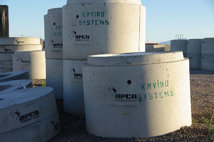
Questions from the Field is a selection of questions NPCA Technical Services engineers received from calls, emails, plant evaluations and comments on blog posts or magazine articles posted to Precast.org
George asks: For a manhole 8 feet in diameter that requires a 1 foot tall and 1 foot wide flange completed in a separate pour, how do I design the dowels to keep the two pieces connected as one structure?
NPCA technical experts answer: First, NPCA engineers are not consultants; however, there is a wealth of technical experience to leverage.
Like most design problems, there are a number of variables that need to be eliminated or calculated before you can arrive at the final answer of how many dowels are needed. Some of those variables include:
- Depth of the manhole
- Weight of the manhole
- Elevation of the assumed water table
- The owner’s/engineer’s required factor of safety against flotation
- Size of dowels to be used
- How deep the dowels will be drilled
- How the dowels are anchored (i.e. grout, epoxy, mechanical anchors, etc.)
- Governing code used to determine the strength of the dowels
- Failure mode of the flange or apron (i.e. dowel pulls out, dowel shears, flange breaks through either bending or shear, etc.)
Each one of the above variables will affect how many dowels are needed, and each variable would need to be addressed before an answer could be determined. Accordingly, the help of a consulting engineer is usually needed to properly solve this kind of problem. However, in lieu of contracting with a design engineer, here is a suggested pathway for a producer to follow to solve this kind of problem on their own.
To address the first three bullet points, NPCA publishes a Buoyancy Guide white paper that may be downloaded at precast.org/resources/producers. There are some suggested values in the white paper to use as a factor of safety, but, before using them, first check the project specs to make sure the owner does not require a greater value.
The rest of the bullet points are much more involved and would either require design calculations to determine or, if the owner is agreeable, you could run a couple of in-plant tests and/or use some conservative assumptions to eliminate them as variables.
In the first case, the design code is very specific about how deep each dowel must be drilled to be able to use the full strength of the steel in the dowel. The code is a little less clear on how to determine how much of that strength is available should the dowel not be embedded the full required length, which is likely the case here. An engineer would need to reference Chapters 22 and 25 of the ACI 318 design code, as well as use a degree of engineering judgement, to calculate the available strength of each dowel.
A suggested alternative would be to run a couple of actual physical in-plant tests and record the results. For example, select a dowel size (i.e., No. 4), drill and dowel the top of a common 1-ton, 2-by-2-by-4-foot eco block. Embed the dowel at the same depth as you would on the manhole wall (i.e. 6 inches), fixing the dowel in place using the proposed method (i.e. grout, epoxy, etc.). Attach a lifting eye to the top of the protruding dowel in the eco block and lift the eco block a couple of inches off the ground. That way, you’ve just proven that a single dowel can accept over a ton of load without pulling out or otherwise failing. If you want to try to reduce the number of required dowels, perform the same test on something heavier, but be ready in case a failure actually occurs.
For the last variable, the failure mode of the flange or apron, a safe assumption would be to use 1.5 times to 2 times the amount of circumferential steel in the apron as you’ve used for the manhole itself. For example, if you’re using a single wrap of 2/8 x W4.0/W2.0 for the barrel of the manhole, use two wraps of the same reinforcing in the flange or apron. In that case, you’re basically ensuring that the manhole wall would have to fail before the flange would, safely eliminating that as a possibility. Also make sure the dowels are not located right at the top or too near the bottom of the flange; shoot right for the middle, about half the depth of the flange.
Putting all of this together, you now have a viable means to figure out how many dowels you need.
As an example, the calculated buoyant force is 36,968 pounds with a factor of safety of 1.31, assuming any factor of safety above 1.25 is acceptable per the project specifications. If you’ve run the physical test(s) and proven that a single dowel can withstand a ton of force without pulling out or breaking, you would simply divide the buoyant force by the maximum 2,000-pound force placed on each dowel, which would be 36,986 lb. / 2,000 lb. = 18.49 = 19 dowels. Divided evenly around the outer circumference of an 8-foot diameter manhole barrel, the dowels would need to be placed roughly 18 inches on center around the manhole. If the actual buoyant force is greater, more dowels would be needed; if the actual buoyant force is less, then fewer dowels would be needed and a greater spacing could be used.
