When we talk about fog, it’s typically the clouds near the earth’s surface that often serve as the backdrop of a horror film. This fog can be frightening, but a different type of fog evokes horror for public health officials in every municipality. Fats, oils and grease, also known as FOG, can build up in sewers and cause partial or complete blockages, which can then lead to sanitary sewer overflows.
One of the most reliable ways to manage FOG and prevent an SSO from occurring is to use a precast concrete gravity grease interceptor. How do we size and design this important piece of infrastructure to maximize its effectiveness? This article highlights the design principles needed to achieve this goal.
FOG’s origins
According to the Environmental Protection Agency, grease from restaurants, homes and industrial sources is the most common cause of reported blockages in sanitary sewer systems.1 FOG is generated every day at restaurants or food service establishments as food is prepared and dishes, utensils and cookware are cleaned. Residential sewer customers can also contribute significant amounts of FOG to the sewer system.
The Water Environment Research Foundation conducted a study in 2008 that led researchers to deduce that FOG deposits are basically metallic soaps.2 The reaction that leads to the formation of this soap begins at discharge. FOG is removed from dishware during cleaning and interacts with excess cleaners and sanitizers to begin saponification, the process that produces soap.
If sufficient amounts of FOG enter the sewer pipes, the resulting product will begin to collect on the top and sides of the pipe. As flow continues, more grease becomes trapped and the buildup continues until the flow is significantly restricted. These masses of FOG can grow dramatically based on the size of the pipe.
FOG has evolved over the years as animal fats such as lard have been replaced by vegetable oils, cleaning agents have changed and hand-washing dishes has been replaced by dishwashers discharging effluent at a higher temperature. Each of these factors plays a key role in the type of grease globule that enters the interceptor.
Grease globules
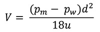
As a grease globule enters a grease interceptor, the globule’s size, density and temperature will impact its destination. Larger globules will rise faster than smaller globules. Calculations of this vertical velocity can be made based on Stokes’ Law.
The formula to calculate velocity of a grease globule is:
Where
V = Velocity of globule (ft./s.)
Pm = density of grease (lbs./ft.³)
Pw = density of fluid (lbs./ft.³)
d = diameter of globule (ft.)
u = dynamic viscosity of fluid (lbs. s./ft.²)
If the density of the globule is less than the density of the fluid, the globule will rise at velocity V, and vice versa. For example, in static water, a 200-micron-diameter grease globule (.00066 feet) with a density of 54 lbs./ft.3 in water with a temperature of 50 degrees Fahrenheit will rise at approximately 0.007 ft./s. If we were to divide that globule size in half to 100 microns (.00033 feet), the globule would rise at 0.002 ft./s. Therefore, for more effective separation, larger grease globules are optimal. Several factors influence globule size, as outlined below.
Oils used in cooking. The type of oil used can affect the rise velocity of the grease globule based on its density. For example, bacon grease has a density closer to 54 lbs./ft.3 (an 8.4-pound difference from water) while zero-trans fat oils are closer to 60 lbs./ft.3 (a 2.4-pound difference from water). The closer the grease’s density is to that of water, the slower it will rise.
Emulsifying cleaners. Detergents used in today’s kitchens may contain emulsifiers to aid in the removal of FOG from dishware and kitchen utensils. Emulsifiers work to prevent FOG from coalescing by reducing the interfacial tension that makes grease globules attract. This process enhances the removal of FOG from utensils and dishware but reduces the size of the grease globules, lessening the ease of separation from the effluent.
Temperature. At higher temperatures, water tends to prevent FOG from coalescing. As such, hotter water may also result in smaller grease globules. Additionally, newer, larger dishwashers can generate a hotter flow. Hot water flow into the grease interceptor containing cooler temperature wastewater can produce a temporary upflow effect due to the lower relative density of the influent stream. However, the short-term impact of this density upflow is minor on the effluent FOG concentration. Over time, the effluent FOG concentration will be similar to previous uniform influent/bulk temperature results.
While grease globules in hot water may be smaller in diameter, fluid also has a lower viscosity at higher temperatures. This allows the globules to rise faster. Also, large-volume precast concrete tanks act as a heat sink and are effective in reducing influent water temperature, which allows for the coalescence of smaller globules.
Stokes’ Law is only applicable in static water, meaning the environment is calm and without velocity spikes and currents. As a result, it’s imperative to maintain a quiescent environment in the tank. According to one WERF study, more effective FOG separation was achieved when fluid velocities near the inlet and outlet were kept below 0.6 in./s.3
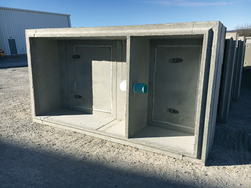
Gravity grease interceptors
The International Association of Plumbing and Mechanical Officials defines a GGI as a “plumbing appurtenance identified by volume and intended to be installed in a sanitary drainage system to intercept, using gravity only, nonpetroleum fats, oils, and greases from a wastewater discharge.”4 It is usually installed underground outside food service establishments, where it can be properly serviced and maintained by qualified personnel. Installing the unit in this location also removes the risk of having used grease stored within the same area where food is prepared and served.
The tank can be made in different shapes and configurations, but must be effective in intercepting the grease. Many factors contribute to the efficiency of a GGI.
Sizing
For some, taking the maximum flow rate in gallons per minute and multiplying that figure by 30 minutes is the extent of the GGI sizing exercise.5 For example, if you expect no more than 75 GPM entering the tank, multiply 75 by a 30-minute retention time and the result is 2,250 gallons. This may work in some situations, but information is being left out of this calculation that may lead to a tank too small or too large for the application.
There are some consistent themes when comparing commonly used formulas for sizing grease interceptors. Most of the sizing formulas consider the maximum flow rate into the tank. It’s the method of establishing this specific influent flow rate that differs from one formula to another. The most commonly used sizing formulas employed in the U.S. include:
- U.S. EPA Method
- Uniform Plumbing Code, 2003, Appendix H
- Uniform Plumbing Code, 2006 and 2009
For the above formulas, calculations are performed based on the following scenario.
XYZ Restaurant, which is located near a highway, is open from 8 a.m. to 8 p.m. The restaurant contains 30 seats and at peak operation produces 40 meals per hour. The 20-foot-by-15-foot kitchen includes the following:
| Appliances | One commercial dishwasher, rated max discharge 25 GPM |
Commercial food grinder, 2-inch trap with 5-GPM capacitySinksPre-rinse sink, 18 inches by 18 inches by 6 inches with 2-inch trap, 1.5-GPM faucet
Special purpose two-compartment sink. Each compartment, 18 inches by 18 inches by 8 inches with 1.5-inch sink drain and trap
Vegetable prep sink, 18 inches by 18 inches by 6 inches, 1.5-inch trap and 1.5-GPM faucet
Wash sink with one set of faucets
Mop basin, 24 inches by 24 inches by 6 inches, 2-inch trap, faucet at 5-GPM maxOtherTwo floor drains, each with 2-inch trap
U.S. EPA method
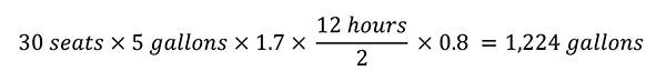
The 1980 version of the EPA formula, which is still used today, calculates the influent flow rate as 5 gallons per meal.
For restaurants, the sizing formula is:

Where
D = Number of seats in dining area
GL = Gallons of wastewater per meal, normally 5 gallons
ST = Storage capacity factor – minimum of 1.7, on-site disposal, 2.5
HR = Number of hours open
LF = Loading factor
-
- 1.25 – interstate freeways
- 1.0 – other freeways
- 1.0 – recreation areas
- 0.8 – main highways
- 0.5 – other highways
For XYZ Restaurant, we would have:
2003 Uniform Plumbing Code, Appendix H Sizing Method
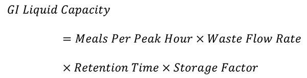
The 2003 Uniform Plumbing Code contained a sizing formula in Appendix H. This formula is similar to the EPA formula, where it is based on hydraulic loading and the storage factor.
The formula is:
Where:
Waste Flow Rate
- With dishwasher – 6-gallon (22.7-L) flow
- Without dishwasher – 5-gallon (18.9-L) flow
- Single-service kitchen – 2-gallon (7.6-L) flow
- Food waste disposer – 1-gallon (3.8-L) flow
Retention Time
Commercial kitchen waste
- Dishwasher – 2.5 hours
Single-service kitchen
- Single serving – 1.5 hours
Storage Factor
Fully equipped commercial kitchen
- 8 hours of operation: 1
- 16 hours of operation: 2
- 24 hours of operation: 3
- Single-service kitchen: 1.5
For XYZ Restaurant, we would have:
![]()
2006 and 2009 Uniform Plumbing Code Method
In 2006, the Uniform Plumbing Code was revised to change the sizing methodology from the Appendix H Method above to a sizing method using drainage fixture units (DFUs). DFUs were developed by Dr. Roy Hunter in 1940 and are assigned to individual fixtures based on their potential load-producing effect on the plumbing and wastewater systems. Chapter 7 of the Uniform Plumbing Code contains tables to be used for this sizing method. Chapter 10 of the Uniform Plumbing Code includes Table 1014.3.6 (Table 1), which has recommended grease interceptor volumes based on total DFUs.
Table 1. Gravity Grease Interceptor Sizing Based on DFUs.7
|
DFUs |
Interceptor Volume |
|
8 |
500 gallons |
|
21 |
750 gallons |
|
35 |
1,000 gallons |
|
90 |
1,250 gallons |
|
172 |
1,500 gallons |
|
216 |
2,000 gallons |
|
307 |
2,500 gallons |
|
342 |
3,000 gallons |
|
428 |
4,000 gallons |
|
576 |
5,000 gallons |
|
720 |
7,500 gallons |
|
2112 |
10,000 gallons |
| 2640 |
15,000 gallons |
To obtain these DFUs, use Table 702.1 from Chapter 7 of the Uniform Plumbing Code, which contains assigned values for many different fixtures (Table 2).
Table 2. Drainage Fixture Values for Various Plumbing and Appliance Fixtures.8

Notes:
- Indirect waste receptors shall be sized based on the total drainage capacity of the fixtures that drain thereinto, in accordance with Table 702.2(b).
- Provide a 2-inch (50-millimeter) minimum drain.
- For refrigerators, coffee urns, water stations and similar low demands.
- For commercial sinks, dishwashers, and similar moderate or heavy demands.
- Buildings having a clothes-washing area with units in a battery of three or more shall be rated at six fixture units each for purposes of sizing common horizontal and vertical drainage piping.
- Water closets shall be computed as six fixture units where determining septic tank sizes based on Appendix H of this code.
- Trap sizes shall not be increased to the point where the fixture discharge is capable of being inadequate to maintain their self-scouring properties.
- Assembly [Public Use (see Table 422.1)].
If DFUs are not known, Table 702.2a of UPC Chapter 7 (Table 3) can be used to assign values based on the maximum DFUs allowed for the pipe size connected to the inlet of the interceptor.
For intermittent flow into the drainage system, DFUs can be calculated based on the rated discharge capacity in GPM using Table 702.2(b) of UPC Chapter 7 (Table 4). A commercial dishwasher would be an example where this table may be used.
For pumps, sump ejectors, air conditioning equipment or similar devices that may continuously flow into a system, 2 DFUs are assigned for each GPM of flow.
Table 3: Drainage Fixture Units Based on Trap and Trap Arm.9
|
Size of Trap and Trap Arm (Inches) |
Drainage Fixture Unit Values |
|
1 ¼ |
1 unit |
|
1 ½ |
3 units |
|
2 |
4 units |
| 3 |
6 units |
| 4 |
8 units |
For SI Units: 1 inch = 25 mm
*Exception: On self-service laundries
Table 4: Drainage Fixture Units based on Intermittent Flow.10
|
GPM |
Fixture Units |
|
Up to 7 ½ |
Equals 1 fixture unit |
|
Greater than 7 ½ to 15 |
Equals 2 fixture units |
| Greater than 15 to 30 |
Equals 4 fixture units |
| Greater than 30 to 50 |
Equals 6 fixture units |
For SI Units: 1 GPM = 0.06 L/s
Note: Discharge capacity exceeding 50 GPM (3.15 L/s) shall be determined by the authority having jurisdiction.
For XYZ Restaurant, we would use Table 1 to get DFUs for sinks, floor drains and the food grinder.
- Special Purpose Sink (1 1/2”): 3 DFUs x 2 basins = 6 DFUs
- Pre-rinse Sink (2”): 4 DFUs
- Vegetable Prep Sink (1 1/2”): 3 DFUs
- Wash Sink (one set of faucets): 2 DFUs
- Mop Basin (2”): 3 DFUs
- Two Floor Drains (2”): 4 DFUs
- Commercial Food Grinder: 3 DFUs
- Commercial Dishwasher: 4 DFUs (based on Table 4 and 25-GPM discharge)
Total: 29 DFUs
Based on Table 1, we would need a capacity of 1,000 gallons. So far, we have three different capacities: 900, 1,000 and 1,224.
One of the issues with using this formula is that while DFU is a common term for plumbers, it is uncommon for pretreatment coordinators and officials dealing with the regulation of GGIs. Also, the DFU does not differentiate between flow from a fixture and flow from a draining sink. When plumbing fixtures do not drain from filled sinks, the faucet flow is used; however, when a filled sink drains, Manning’s Equation should be used to determine the peak allowable flow.
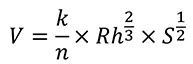
Where
V = cross-sectional mean velocity (ft./s. or m./s.)
k = 1.486 for U.S. units and 1.0 for SI units
n = Manning coefficient of roughness (Represents the roughness or friction applied to the flow by the channel. This depends on the material. For example, smooth concrete and steel has an n value of around 0.012. PVC values range from 0.009 to 0.011.)
Rh = Hydraulic radius (ft., m.) This is equal to A/Pw, where A is the cross-sectional area of flow in ft.3 or m.3 and Pw is the wetted perimeter in ft. or m.
S = Slope (ft./ft. or m./m.)
Officials from the town of Cary, N.C., developed a spreadsheet that allows for input of the various fixture types, sizes and characteristics for the calculation of the maximum flow rate into a GGI.11
Using XYZ Restaurant data along with the assumption of 75-psi water pressure, a 30-minute retention time and a 25% storage factor, the maximum flow rate is 51.69 GPM. The resulting tank size is 2,132 gallons.
By using four different formulas, we’ve obtained grease interceptor volumes of 900, 1,000, 1,224 and 2,132 gallons, representing a 137% increase from the lowest to the highest value. These varying capacities can lead to some confusion.
The volume calculated via the town of Cary, N.C., equation represents a bit of an outlier, but it also is the most thorough, incorporating many factors the other equations do not. One WERF study references this spreadsheet and comments on the use of the maximum flow rate for the sizing of a GGI.12 This flow rate is very conservative and highly unlikely because all fixtures would have to be running and all sinks would have to be draining simultaneously.
According to the study, observations of GGIs in the field revealed that 1/3 of the maximum flow rate would be appropriate for design. Applying this to XYZ Restaurant, the flow rate would drop to below 20 GPM, thus requiring a 750-gallon tank.
In 2009, the National Precast Concrete Association published a white paper covering design considerations for precast GGIs.13 The authors recommended that the 2003 UPC, Appendix H Method for sizing precast GGIs be used when no other code is specified or provided. However, the white paper did not include any data from the WERF studies mentioned above. As such, until further research is conducted, there is no “right” or “wrong” formula to use. Still, taking the maximum flow rate and multiplying by retention time is an ineffective approach, and leaves out many key factors.
In deciding what formula to adopt, the authority having jurisdiction should ensure the formula is clear so that the assumptions behind the flow calculations are known.
Design
Grease interceptors work to remove FOG and other materials through separation by gravity or flotation. These mechanisms are time-dependent, so the design of the tank must allow for an appropriate amount of retention time and for a calm environment beneath the liquid level. Velocity spikes must be minimized to allow for separation and to avoid potential interaction with previously separated FOG or solids layers. The accumulation of FOG and solids layers will effectively reduce the clear zone and will result in slightly accelerated velocity of fluid through the tank. This reinforces the importance of periodic maintenance and cleaning of the tank. Tank designs should enhance the ability to clean and maintain the interceptor.
Compartmentalization of GGIs is common to achieve more separation. Two compartments are common, and three compartments are also sometimes specified. Although it is intuitive to assume that multiple compartments will yield more separation, this is not always the case. The effectiveness of the compartments depends on the connection hole or baffle system.
The Venturi effect, named after Italian physicist Giovanni Battista Venturi, describes how a fluid velocity must increase as it passes through a constriction (Figure 1).
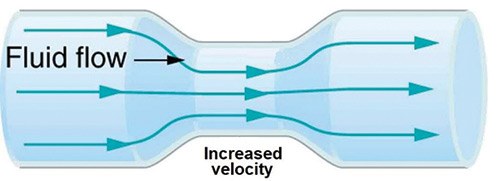
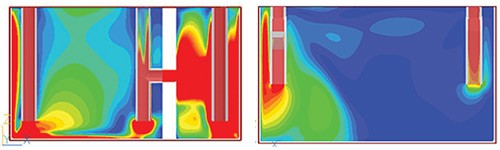
When smaller holes or baffles are used to transfer fluid from one compartment to another, the resulting increased velocity of the fluid can cause the system to short circuit. The WERF study demonstrated that in some cases, single-compartment tanks performed better than dual compartment tanks for this very reason (Figure 2). Therefore, compartment walls should be designed to distribute the flow and minimize the occurrence of high local fluid velocities. Larger slots or transfer ports are recommended.
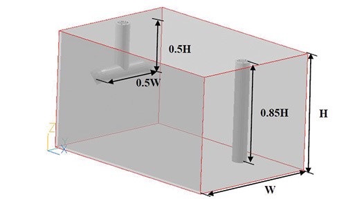
The same study also shows that local fluid velocities could be reduced by distributing the flow across a larger cross-sectional area. Ideally, the area would occupy the entire cross-section of the of the grease interceptor (i.e., depth times height), as this setup would provide the lowest fluid velocities. To achieve this, the influent baffle would have to be designed to distribute the incoming flow (Figure 3).
Precast peace of mind
A properly functioning precast concrete GGI is key to keeping FOG-related issues from occurring in the treatment field or sewer system. The tank’s performance will depend on its sizing and design. While flow rate is important in sizing, it is not the only factor that should be considered. Designing the tank to provide ease of maintenance while also maximizing retention time and creating a quiescent environment is essential for separation effectiveness.
Precast concrete GGIs not only provide greater storage capacity and longer retention times, but also offer the added benefits of structural integrity, design flexibility and a long service life. Outdoor concrete interceptors provide a level of health safety by removing this process from the food preparation environment. They also shift the maintenance responsibility from kitchen staff to third-party maintenance contractors, providing additional quality and safety assurance. As such, precast concrete GGIs are an efficient solution to a critical challenge, offering peace of mind to environmental professionals and facility owners.
Claude Goguen, P.E., LEED AP, is NPCA’s director of sustainability and technical education.
Read the accompanying “Watertightness Testing for Septic Tanks and Grease Interceptors” story or take the associated online exam.
Endnotes
- https://www3.epa.gov/npdes/pubs/pretreatment_foodservice_fs.pdf
- https://www.iwapublishing.com/books/9781843395232/fats-roots-oils-and-grease-frog-centralized-and-decentralized-systems
- ndwrcdp.org/documents/03-CTS-16T/03CTS16TAweb.pdf
- iapmo.org/California%20Plumbing%20Code/Chapter%2002.pdf
- Metcalf & Eddy, Burton, F. L., Stensel, H. D., & Tchobanoglous, G. (2003). Wastewater engineering: treatment and reuse. McGraw Hill.
- Otis, R. J., Boyle, W. C., Clements, E. V., & Schmidt, C. J. (1980). Design Manual; Onsite Wastewater Treatment and Disposal Systems. Environmental Protection Agency Report EPA-625/1-80-012, October 1980. 412 p, 86 Fig, 82 Tab, 204 Ref. 1 Append.
- Uniform Plumbing Code, 2015
- Uniform Plumbing Code, 2015
- Uniform Plumbing Code, 2015
- Uniform Plumbing Code, 2015
- ndwrcdp.org/documents/03-CTS-16T/GISizingSpreadsheetversion.xls
- https://www.werf.org/a/ka/Search/ResearchProfile.aspx?ReportID=03-CTS-16Tb
- https://precast.org/wp-content/uploads/2014/08/Grease_Interceptor_Design.pdf