There is a great need for a durable precast concrete floor structure that is lighter, stronger and more energy efficient, and one that can be manufactured in variable sizes. Nowhere is this need greater than in areas devastated by storms, particularly in New Jersey’s rebuilding efforts after Superstorm Sandy. A new concrete floor plank system offers many advantages for post-disaster rebuilding efforts. Test results (see the sidebar “Load Testing of Precast Concrete Plank”) compare the system’s greater strength and durability compared with other building materials.
A look at traditional and new precast floor systems
Traditional hollowcore precast concrete floor panels used in residential and multi-story buildings have been the go-to product for many years, and with good reason. Hollowcore floor systems have many advantages that have made them the backbone of sustainable, durable precast concrete building components. To help reduce flooring weight for transportation, erection and foundation loading, hollowcore precast concrete planks are cast with continuous circular voids running through the panel’s length. For added strength, prestressing strands are cast into the panels during production. With its top and bottom longitudinal flanges, hollowcore is an exceptionally strong structural component that is used to span large areas between building columns and walls.
Some of the advantages of the newly developed floor system include:
- Decreased panel weight (almost half the weight of traditional systems) allows smaller column or wall sections to safely carry the floor loading.
- Smaller and lighter columns and walls help to minimize the building’s foundation dimensions, or project footprint, and thus reduce project costs.
- Reduced seismic design load requirements are possible with less weight.
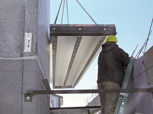
- More efficient transport and job-site delivery are possible with lighter panel weights. Because the pieces are easier to tilt on the truck, more space is available so more product can be delivered per shipment to the job site (see Figure 1).
- Design flexibility and construction efficiency are increased because planks can be manufactured in various widths.
- The new panel system costs less and is more efficiently produced than traditional precast concrete floor systems.
- It offers increased resistance to flood and seismic forces.
- Thin topping means the deck may be as thin as 1 in.
- Successful load testing for several types of loading (distributed and concentrated) showed good system performance results.
- Energy efficiency of insulated precast planks reduces heat loss and energy bills in commercial and residential construction, which may help contribute to project LEED points (see Figure 2)
- Greater tensile loads are carried by the incorporation of prestressed strands in the stems and mild reinforcing in the deck.
A closer look at the new floor system
Here are some of the design and installation details of the precast concrete planks:
Stems: The floor panel is comprised of a topping (or deck) supported by a number of parallel, longitudinal concrete stems that extend along the length of the panel. The concrete stems extending between the end blocks are spaced 2 ft on center. Each stem has a depth of 6 in. to 16 in. and a width of 2 in. to 15 in., depending on design loads.
End blocks: Two transverse end blocks support the deck. Located at plank ends, the concrete blocks have a minimum thickness of 2 in. End blocks are formed with (and protrude from) the deck and run along the panel’s width.
Bearing surface: Made of solid concrete, the blocks form a continuous bearing surface for mounting the floor panels on top of wall members, and these blocks subsequently support the walls for the next level (see Figure 3).
Storage and transportation: The end blocks also prove useful for stacking, storage and transportation.
Post-tensioning: Each end block has an opening along the panel width for post-tensioning after the floor is installed on the bearing walls. Post-tensioning helps to distribute wind, seismic or any other lateral forces on the bearing walls.
Insulation: A 1-in. to 3.5-in. thickness of molded expanded polystyrene insulation can be attached to the panel bottom. Insulation extends around the stems, the bottom portion of the deck, and the inside portion of the end blocks between the stems. Insulation provides important thermal resistance and noise dampening for building occupants.
Metal wall stud: A metal wall stud, attached to the insulation at the bottom of each stem, can be used for attaching drywall or other finish materials. An optional lightweight, nonstructural leveling coat may be applied to the top deck.
Installation: Each building level’s floor is formed with a number of precast concrete panels set side by side. Panels are mechanically connected along their lengths. These connectors are welded together once the panels are installed.
Connections and voids: Connectors help distribute wind, seismic or any other lateral forces to the floor panels. Vertical holes or channels may be manufactured per specification or cut in the field for plumbing, electrical conduit or any other utility runs. Field-cut utility openings are easily accommodated for construction change orders.
Rebuilding with a stronger floor system
This new floor system is currently being used in rebuilding work along the Jersey Shore, which took a direct hit from Superstorm Sandy in October 2012. With many coastal areas of the Atlantic Coast incurring the greatest damage from the record-breaking hurricane’s destructive force, rebuilding efforts must consider the most resilient building materials for sustainability, public safety and flood insurance (see Figure 4). Strong precast concrete walls and advanced floor systems provide a dry, warm, damp-resistant and exceptionally energy-efficient structure for family and commercial residents.
Recent changes to FEMA’s flood zoning and insurance guidelines make it clear that we can no longer afford to rebuild with the inferior building materials of the past.
Mohamed Mahgoub, Ph.D., P.E., is assistant professor and Concrete Industry Management (CIM) program director at the New Jersey Institute of Technology, and an industry expert in bridge rehabilitation, inspection, rating, design and analysis. Dr. Mahgoub may be reached at mahgoub@njit.edu.
Sidebar
Load Testing of Precast Concrete Plank
Testing was performed in July 2012 to analyze the performance of a new floor plank system under maximum loading.
After each increment of weight was applied, deflection was measured again, the plank was inspected at mid-span for cracks, and the strands were checked at the end of the plank for slippage. The load was increased incrementally until there was a point load of 10.8 kips at mid-span, in addition to the 52 ft-kip load initially applied. At this point, the panel had deflected more than 8 in., with the last weight increase having increased the deflection by 3 in.