Know your systems and materials in order to keep everything together
In an ideal world, all precast concrete structures would be cast at the plant monolithically in a single high-quality section.
In the real world, limitations such as transport dimensions and handling weight force us to cast structures in multiple sections.
The performance of the entire modular system depend on the quality of the joint system and material between adjacent sections.
For typical buried precast structures, joint configurations are based on performance needs and the current ASTM standards available to specify them.
Knowing what type of joint to specify
Proper precast structure joint design starts with appropriate performance requirements to meet a project application. Higher requirements translate to higher risk and, consequently, higher cost.
Specifying leak resistant pipe and structure joints along with resilient rubber booted structure connections may not be the optimum economical design if that same structure also accepts perforated subsurface drainage pipes.
Similarly, a sanitary sewer structure placed in the ground with a high water table requires the highest available leak resistant joint system to minimize any groundwater added to the effluent, which creates significant long-term treatment costs at the wastewater treatment plant.
Finding this balance often is the result of decades of experience with appropriate design performance. For new designers, though, two main resources are available to assist.
Joint design resources
The American Association of State Highway and Transportation Officials (AASHTO) in 2009 adopted “PP-63 Pipe Joint Selection of Highway Culvert and Storm Drains,” now designated AASHTO R 82, which provides guidance for designers to specify the appropriate performance requirements for different pipe jointing systems based on four defined field performance expectations.
- Soil tight
- Silt tight
- Leak resistant
- Special design
As the title suggests, this guide is geared toward pipe joints. However, the terms, concepts and methodology equally are appropriate for precast structure joints on manholes, storm inlets, vaults and other buried precast structures.
Each joint type is defined as follows:
- Soil-tight joint. A joint that is resistant to infiltration of particles larger than those retained on the No. 200 sieve (openings measuring 0.003 inches or 0.75 mm). Soil-tight joints provide protection against infiltration of backfill material containing a high percentage of coarse grain soils and are influenced by the size of the opening (dimension normal to the direction that the soil may infiltrate) and the length of the channel (length of the path along which the soil may infiltrate).
- Silt-tight joint. A joint that is resistant to infiltration of particles that are smaller than particles passing the No. 200 sieve. Silt-tight joints provide protection against infiltration of backfill material containing a high percentage of fines and typically utilize some type of filtering or sealing component, such as an elastomeric rubber seal or geotextile.
- Leak-resistant joint. A joint that limits water leakage at a maximum rate of 200 gallons/inch-diameter/mile/day for the pipeline system considering the project-specified head or pressure.
- Special-design joint. Joints requiring special strength in bending, shear or pull-apart capabilities or unusual features such as restrained joints placed on severe slopes, welded joints or flanged and bolted joints for high pressures, high heads or velocities. These typically are described within special provisions of the project specifications.
Included within the guide is a helpful flow diagram describing differing project design performance requirements and the appropriate joint system to be employed within the four groups.
From a practical design standpoint, engineers often simply differentiate between the need for a silt-tight joint system or a leak-resistant joint system. For precast structures, special-design joints typically relate to additional considerations relating to structural loading – shear or lateral – special assembly or restrained joint needs rather than leakage requirements.
This guide provides clarification on terms and is a training tool for an engineer who may not be familiar with buried precast structure performance and plant verification criteria.
Another resource is local precast industry representatives. This could be through a local or regional precast association or directly with the precast production facilities within the project location.
Though there are nationally recognized ASTM standards describing differing joint systems and plant testing verification methods, not all are commercially available throughout North America. A listing of NPCA Certified Plant members with contact information showing their locations and precast product lines can be found on the NPCA website.
ASTM C13.08 & ASTM joint standards
Once a joint performance criterion is established, a specific joint type or sealing system often is described or specified within project requirements. Project documents benefit by referencing various ASTM joint standards that have been specifically developed for precast concrete pipe and structure joints.

The ASTM subcommittee solely responsible to develop and maintain current standards for precast pipe and structures is C13.08 “Joints for Precast Concrete Structures.” This subcommittee meets twice each year to review and update existing standards and to develop and ballot new joint standards. Currently, the ASTM standards pertinent to buried precast concrete structures are:
- C443. Standard Specification for Joints for Concrete Pipe and Manholes, Using Rubber Gaskets
- C877. Standard Specification for External Sealing Bands for Concrete Pipe, Manholes, and Precast Box Sections
- C990. Standard Specification for Joints for Concrete Pipe, Manholes, and Precast Box Sections Using Preformed Flexible Joint Sealants
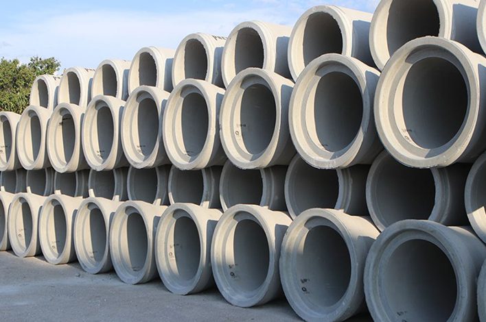
Most precast joint configurations focus on pipe joints. The horizontal orientation of a buried pipe joint introduces differential shearing loads across the joint that requires the sealing mechanism to be evaluated in different scenarios. This not only includes an ideally homed joint in a centered position but also a joint deflected position, typically opened not less than a half-inch on each side.
Buried joints also need to be analyzed in an off-center position or shifted to a point of concrete-to-concrete contact between the bell and spigot on one side of the joint and maximum open annular space on the opposing side of the joint.
For buried precast structures, the typical jointed connections are oriented vertically. This important distinction provides joint sealing benefits not realized when compared with the horizontal pipe joint orientation.
The first alteration is the weight of the newly joined structure bearing down upon the previously installed section. This load provides a high uniform force to “home” the joint and maintain the connecting force throughout the installation. This downward force is beneficial for joints utilizing flexible bitumen or butyl rope sealants – per ASTM C990 – as the primary means to meet or exceed traditional joint performance expectations.
A flexible sealant is placed on the joint surface where the two sections bear against each other. This is the end of the groove onto the tongue shoulder or vice versa. It is important for the joint forming equipment and the facility’s production practices to provide uniform joint surfaces of the two mating sections that do not exceed the specified gap between the two at any location. This typically is 3/8 inch prior to sealant placement per ASTM product standards for septic tanks (ASTM C1227) for gravity grease interceptors (ASTM C1613) and water and wastewater structures (ASTM C913) or less if required by sealant manufacturer.
Another accepted design assumption for vertical joint orientation is that mated joints maintain a centered position because of uniformly placed backfill around the structure perimeter to eliminate side shearing loading. For circular sections, this creates a uniform annular space between the bell surface and spigot surface as defined within ASTM C443. (Figure 2)

For joints using elastomeric gaskets (per ASTM C443) as the sealing medium, this provides uniform gasket deformation through the entire joint perimeter and a higher assurance of leak resistance. Elastomeric gaskets as a sealing mechanism require a much higher level of tolerance in the concrete joint than a flexible rope sealant system. The precast production process needs to implement pre- and post-pour production practices to ensure tolerance levels are being met.
Since the turn of the 20th century, precast farm drainage tiles have utilized external joint wraps to keep joints soil tight. The original tar paper wraps have given way to a variety of non-woven geotextiles that when properly applied provide superb silt and soil tightness both horizontally and vertically.
Additionally, the use of high quality, impervious joint wrap systems (ASTM C877) provide leak resistance when installed in accordance with the manufacturer’s requirements. Like other joint systems, vertical precast structure joint installation of external joint wrap systems is less cumbersome than placing the same wrap system around and under a horizontal pipe joint, in and through the pipe bedding. A vertical precast structure joint is up out of the soil with all sides easily exposed, clean and accessible.
Quality joints, quality structures
The inground performance history of buried precast concrete structures have shown them to be the most adaptable, constructable, resilient, durable and cost-effective when compared to other alternate products on the market.
Transportation and construction handling limits often require a precast structure to be comprised of many adjoining precast components. With such a segmental connection, there might be a design concern that the joint areas would be problematic toward the structure performance expectations. However, with the many joint options available to meet and exceed the appropriately specified joint performance needs, these connections are no “weak link” within the chain of a quality precast system.
Eric Carleton, P.E., is a former director of codes and standards at NPCA. He is an ASTM fellow and former chairman of C13.08 Precast Concrete Joints subcommittee.